Last week I was trying to debug a breaking CP-SAT circuit constraint. The error message just said that the graph was broken, and listed the tails and heads that made up the newtork. Those lists are hard to read, and I was grubbing around trying to manually pair up each tail with each head in a spreadsheet. But then I remembered that I’m a programmer, and so I wrote a small utility to leverage Graphviz to visualize the circuit constraint graph. This post writes up that chunk of code and how I’ve been using it to clean up my circuits.
Failing circuit constraints
When I first started with the OR-Tools CP-SAT solver, my thought was that the routing solver would “soon” be ported over to the CP-SAT engine, so I’d better learn the new semantics. This still hasn’t happened, but I’m glad I put in the work as the CP-SAT solver can do more complicated things than the routing solver.
That said, setting up the circuit constraint properly can be a chore. With the routing solver, everything is handled for you behind the scenes. You tell the API how many nodes are in your problem, and it will create the logical network for you. Sure you still have to lay out the rules about which nodes are paired (for example, for pickup and delivery), and which vehicles can visit which nodes, and you have to track things like dimensions for time and vehcle loads, but you don’t have to lay out the network itelf.
In the CP-SAT circuit constraint, you do have to specify the network by hand. For example, the project I am currently working on is a “simple” pickup and delivery and back again problem. One job has several steps, from leaving the warehouse, to arriving at the venue, to eventually returning to the warehouse. The jobs also might be too large for a single truck, and must be spread over multiple trucks. Then there are conditions about which trucks are preferred, which crew members can drive which trucks, and so on. All of these “extra” conditions are why CP-SAT is perfect for the problem, but with that power comes the need to manually build up the circuit constraint.
I don’t want to get into too much about the nuts and bolts of the use case, as it is irrelevant to this post. Instead what I want to do is present my code for visualizing the circuit constraints.
Plotting a circuit constraint
When I create a circuit constraint, I populate two structures that are basically identical. These are:
    vehicle_arcs: list[cp_model.ArcT] = []
    vehicle_literals: dict[tuple[int, int], cp_model.LiteralT] = {}
In the cp_model.py file, the structure ArcT is defined as:
ArcT = tuple[IntegralT, IntegralT, LiteralT]
So they are both storing the same thing, but my dictionary lets me more easily grab the literal for a node pair. That is why my link generation function populates both of these structures:
def add_arc(
    model: cp_model.CpModel,
    arcs: list[cp_model.ArcT],
    literals: dict[tuple[int, int], cp_model.LiteralT],
    i: int,
    j: int,
):
    if (i, j) in literals:
        return
    literals[i, j] = model.new_bool_var(f"lit_{i}_{j}")
    arcs.append((i, j, literals[i, j]))

...  later  ...

    vehicle_arcs: list[cp_model.ArcT] = []
    vehicle_literals: dict[tuple[int, int], cp_model.LiteralT] = {}
    for node, record in enumerate(records):
        # can it be first
        if node_can_be_first(record):
            add_arc(model, vehicle_arcs, vehicle_literals, 0, node + 1)
            vehicle_source_literals.append(vehicle_literals[0, node + 1])
        # can it be last
        if node_can_be_last(record):
            add_arc(model, vehicle_arcs, vehicle_literals, node + 1, 0)
        # no original nodes can be skipped if they need a driver.  But child nodes can
        if node_can_be_skipped(record):
            # can be skipped, but large penalty if skipped
            add_arc(model, vehicle_arcs, vehicle_literals, node + 1, node + 1)
            skip_lit = vehicle_literals[node + 1, node + 1]

            # maybe do something with the skip literal, like this is how I would
            # handle something like a disjunction from the routing solver world
            obj_coeffs.append(10000000000)
            obj_vars.append(skip_lit)
        for next_node, next_record in enumerate(records):
            # can next_node come after node
            if node_can_follow(record, next_record):
                add_arc(model, vehicle_arcs, vehicle_literals, node + 1, next_node+1)
    model.add_multiple_circuit(vehicle_arcs)

... etc ...
Plotting the generated circuit
The first reason I turned to graphviz was to make sure I was creating the graph I thought I was. It is easy enough to just print all of the records, as in:
for a, b in vehicle_literals.keys():
    print(f"{a} -> {b}")
I have done that and it works fine. But it is certainly quite tedious to read through each line and remember which node is which, and so on. My first plotting attempt was to just dump the tail to head pairs in such a way that they can be ingested easily as a text file to graphviz (well, at the time I was using quarto, so I was dumping a qmd file with some other debugging information).
dot_plot_header = """
```{dot}
//| fig-responsive: false
//| fig-width: 1800px
//| fig-height: 2000px
digraph finite_state_machine {
        fontname="Helvetica,Arial,sans-serif"
        node [fontname="Helvetica,Arial,sans-serif"]
        edge [fontname="Helvetica,Arial,sans-serif"]
        node [shape = circle];
        rankdir=LR;
"""

dump = []
for entry in vehicle_arcs:
    node = entry[0] - 1
    next_node = entry[1] - 1
    a = "sink"
    b = "sink"
    if node >= 0:
        record = steps_df.loc[node]
        a = f"{record.location_type} {record.event_type} {record.copy_idx}"
    if next_node >= 0:
        record = steps_df.loc[next_node]
        b = f"{record.location_type} {record.event_type} {record.copy_idx}"

    dump.append(f'\n  "{a}" -> "{b}";')
print(dot_plot_header)
print("".join(dump))
print("```")
That solution was less tedious than reading rows of “1 -> 2”, and it meshed well with my documentation cycle in quarto documents, but it still required an extra step of rendering the quarto document.
So I finally just wrote a small function to use pygraphviz.
def print_graph_from_formulation(
    arc_literals: dict[tuple[int, int], cp_model.LiteralT],
    filename: str = "circuit_constraint_formulation.svg",
):
    """Parse the circuit constraint error to build a plot, and plot it"""

    A = pgv.AGraph(directed=True, strict=True, rankdir="LR")
    for (a, b), lit in arc_literals.items():
        A.add_edge(a, b, label=f"{lit}")

    A.layout("dot")
    A.draw(filename)

...  later, after building the circuit  ...

    if len(jobs) < 3:
        # very large job runs can bog down the plot function
        file_tag = "-".join(str(j.id) for j in jobs)
        print_graph_from_formulation(
            vehicle_literals, f"circuit_constraint_formulation_{file_tag}.png"  # or svg, etc
        )
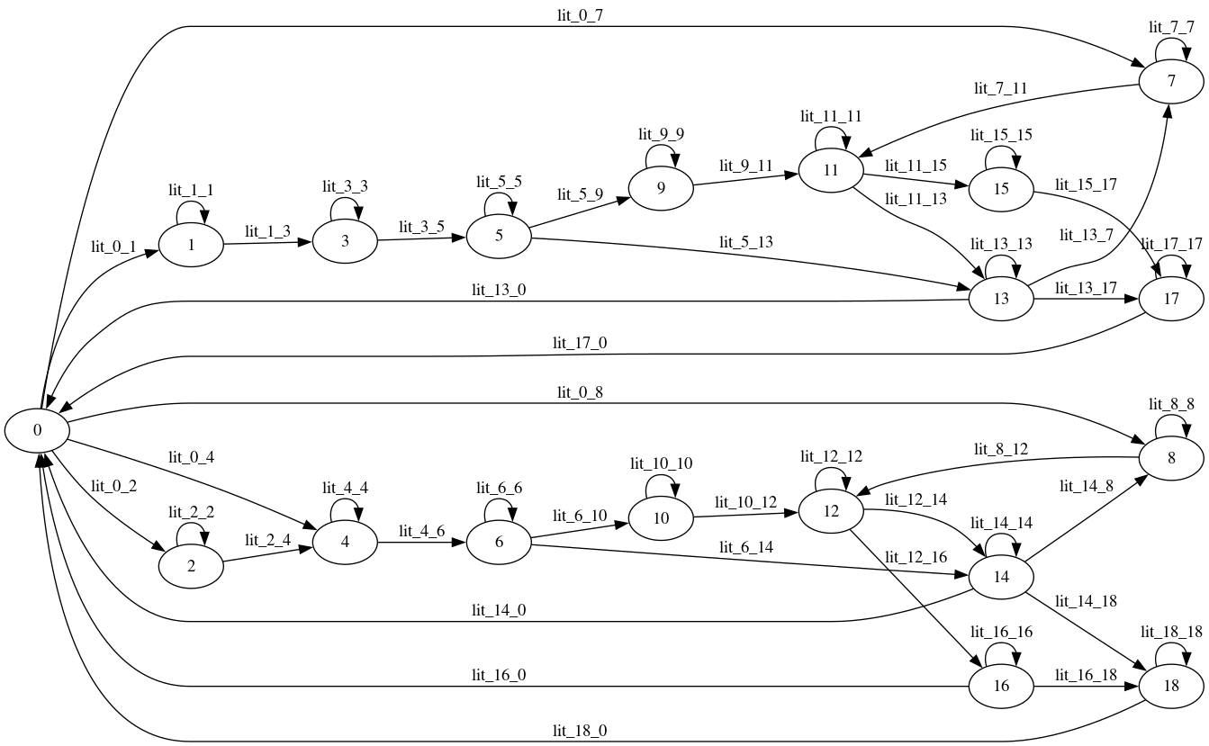
For a single job, this plot function will generate the following representation of the circuit constraint formulation. This tells me at a glance that the problem will allow at most two vehicles to serve the job, and that extra link from the origin to node 4 shows that I’m allowing the second vehicle to start with pickup crew members (in case it is only needed to transport crew).
Using the plotter to help with debugging
The real insight I gained after writing and using this plotting function is that the CP-SAT solver will simplify the graph it receives. So when it finds an error in the circuit constraint formulation, it is not necessarily a problem with the circuit constraint generation code.
What the solver does behind the scenes is to analyze and apply all of the constraints it knows about. That includes all of the enforcement literals and constraints that might in turn govern the state of the literals in the circuit constraint. Unfortunately, once I fix a problem I don’t make a habit of keeping that bug around, so this example is a little bit artificial. However, in the earlier code you will see that after the links from the source to the starting nodes, I keep track of the literals:
    for node, record in enumerate(records):
        # can it be first
        if node_can_be_first(record):
            add_arc(model, vehicle_arcs, vehicle_literals, 0, node + 1)
            vehicle_source_literals.append(vehicle_literals[0, node + 1])
These source literals are the start of a loop through the circuit constraint, as this is a multiple circuit constraint. Because it fits the business logic, I am restricting each vehicle to at most one loop through the circuit. One of the ways I do this is to use the following constraint:
model.add(sum(vehicle_source_literals) == sum(veh_active))
I have another constraint that makes sure that each vehicle can have at most one start, but that is irrelevant here.
If I change the above constraint to the following:
model.add(sum(vehicle_source_literals) == 0)
then the solver knows a priori that none of the literals outbound from the source can be true. This results in an infeasible model, with the complaint:
INFEASIBLE: 'routes: node 0 misses incoming or outgoing arcs'

Unsat after presolving constraint #506 (warning, dump might be inconsistent): routes { tails: 1 tails: 2 tails: 3 tails: 4 tails: 5 tails: 6
tails: 7 tails: 8 tails: 9 tails: 10 tails: 8 tails: 8 tails: 8 tails: 8 tails: 9 tails: 9 tails: 10 tails: 10 heads: 1 heads: 2 heads: 3
heads: 4 heads: 5 heads: 6 heads: 7 heads: 8 heads: 9 heads: 10 heads: 0 heads: 8 heads: 5 heads: 10 heads: 9 heads: 10 heads: 0 heads: 10
literals: 672 literals: 674 literals: 676 literals: 678 literals: 682 literals: 684 literals: 686 literals: 690 literals: 693 literals: 696
literals: 689 literals: 690 literals: 691 literals: 692 literals: 693 literals: 694 literals: 695 literals: 696 }
So I needed to do a few things here. First of all, I wanted to verify that what I was generating in my code was actually what ended up in the model that was sent to the solver. So when a problem is infeasible, I have a new bit of code that loads up the saved, infeasible model from its “pbtxt” dump, and reads in anything that looks like a circuit constraint:
def parse_model_for_routes(
    model: cp_model.CpModel,
) -> str | None:
    """Parse the savedsolver error reponse for something meaningful"""
    model_proto: cmh.CpModelProto = model.Proto()
    model_constraints = model_proto.constraints
    for i, c in enumerate(model_constraints):
        if c.routes is not None:
            if (
                c.routes.tails is not None
                and len(c.routes.tails) > 0
            ):
                print_graph_from_constraint(
                    c, model, f"circuit_constraint_{i}_from_saved_model.png"  #  or "svg", which is what I usually use
                )
That function of course calls a slightly different plotting function:
def print_graph_from_constraint(
    constraint: cmh.CpModelProto,
    model: cp_model.CpModel,
    filename: str = "circuit_constraint_error.svg",
):
    """Parse the circuit constraint error to build a plot, and plot it"""
    model_proto: cmh.CpModelProto = model.Proto()
    model_constraints = model_proto.constraints
    model_variables = model_proto.variables
    # the saved protobuf is in terms of matched lists of tails, heads, and literals
    tails = list(constraint.routes.tails)
    heads = list(constraint.routes.heads)
    literals = list(constraint.routes.literals)
    var_lits = [model_variables[l] for l in literals]
    network = [(t, heads[i]) for i, t in enumerate(tails)]
    edge_labels = {(tails[i], heads[i]): lit for i, lit in enumerate(literals)}

    A = pgv.AGraph(directed=True, strict=True, rankdir="LR")
    for i, e in enumerate(network):
        A.add_edge(e, label=f"{var_lits[i].name}")
    if len(tails) > 200:
        # hard for dot to do
        A.layout("sfdp")
    else:
        # dot looks better, but takes forever on large graphs
        A.layout("dot")
    A.draw(filename)
This generated the following graph, which matched my formulation (note that this is with a different problem than the above plots, so it doesn’t match those, but it does match this problem’s input formulation plot exactly):
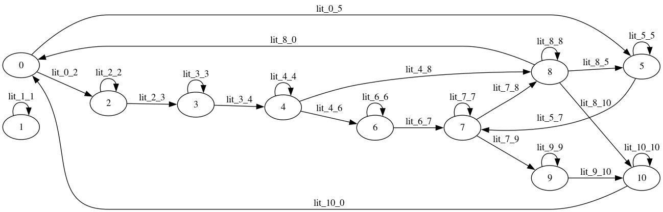
So I was able to confirm that my input wasn’t the problem. The other hint is the solver error itself. I parse that with the following code:
routes_line_regex = re.compile(
    r"INFEASIBLE: 'after loading constraint during probing (routes\s*.*})\'"
)

...

def parse_response(
    result: str,
    model: cp_model.CpModel,
) -> str | None:
    """Parse the solver error reponse for something meaningful"""
    match = parse_response_string(result)
    if match is None:
        return None
    # still here, then something useful was reported
    # use regex patterns
    stripped_result = "".join(result.splitlines())  # strips out multiline
    ...
    match = routes_line_regex.search(stripped_result)
    if match:
        # the regex strips the parts I don't care aboout
        matched_failing_constraint = str(match.group(1))
        if matched_failing_constraint:
            _report.append(
                "The solver reported a problem with a circuit constraint.  See the generated buggy_circuit plot file."
            )
            print_graph_from_constraint(matched_failing_constraint, model, "buggy_circuit.png")
    ...
Here I could again use the print_graph_from_constraint version of the plotter, as the reported error is still in the protobuf format, even though it has been reduced from the original version. This “buggy circuit” plot looks like this:
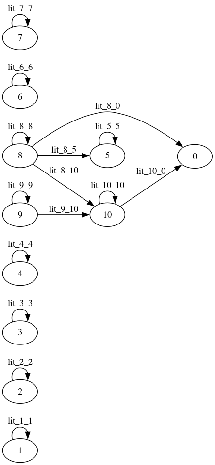
This plot is obviously NOT a valid graph. There are several nodes that are not part of a circuit: you can’t get to nodes 8 or 9, and you can’t get out of nodes 5 or 0. While the self-loops fixup 5, 8 and 9, node 0 is only a sink, never a source, and so cannot be in a Hamiltonian cycle.
While it is obvious right now that the error is no outputs from the source node (0), when I actually ran into exactly this problem it took a little bit of thinking and a short bike ride to realize that I had probably messed up the veh_active array. I was doing a bunch of refactoring trying to speed up the solver formulation, and somewhere in that the vehicle usage literals were not properly saved to the veh_active array. Once I fixed that, the circuit constraint was working fine.